Hey everyone,
If you’re working with current transformers (CTs) in power systems—whether you’re an electrical engineer, a maintenance tech, or someone just getting into the game—you’ve probably heard the term “ratio error” thrown around. But let’s be real, it’s not just another jargon word to memorize. For us CT suppliers, ratio error is the backbone of why our products work (or why they don’t work) when your facility is measuring current, protecting equipment, or keeping the grid stable. Let’s break this down like we’re chatting over coffee—no boring textbook fluff, just the stuff that actually matters. Current Transformer
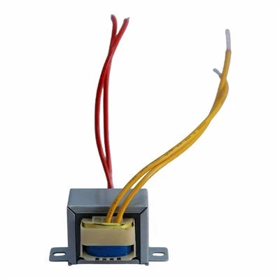
First, let’s start with the basics: what’s a CT, anyway? In case you’re new, a current transformer is a device that steps down high AC currents (think: thousands of amps running through power lines) to a safe, low level (usually 5A or 1A) that your meters, relays, or sensors can handle. It’s like a translator between the big, scary power world and the small, precise devices you use to monitor it.
Now, the “ratio” part. Every CT has a nameplate ratio—that’s the number like 200:5, which means if the primary current (the big one going through the line) is 200A, the secondary current should be exactly 5A. That’s the ideal scenario. But in the real world, nothing’s perfect. That’s where ratio error comes in.
So, what exactly is ratio error? Let’s keep it simple: it’s the difference between the actual secondary current your CT produces and the secondary current it should produce, divided by that ideal secondary current, multiplied by 100 to get a percentage. The formula looks like this (I’ll keep it super casual):
Ratio Error (%) = [( (Ideal Secondary Current) – (Actual Secondary Current) ) / Ideal Secondary Current] × 100
Wait, let’s test that with an example. Suppose you have a 200:5 CT. If the primary current is 200A, the ideal secondary is 5A. But say your actual secondary current is 4.95A. Plugging in the numbers: [(5 – 4.95)/5] ×100 = 1% ratio error. Easy, right?
But hold up—why does this matter so much? Let’s get to the “so what?” part. If ratio error is off, your measurements are wrong. If your meter reads 1% less current than what’s actually flowing, your energy bills could be off (either you overpay or underpay, and trust me, utilities hate that). Worse, if you’re using a CT for protection—like a relay that trips when current gets too high—wrong ratio error could make the relay trip too early, leading to downtime, or not trip at all when there’s a fault, which can fry expensive equipment. For our team here, ratio error isn’t just a spec on a sheet—it’s about making sure your facility stays online, your bills are accurate, and no one’s dealing with a avoidable outage.
Now, what causes ratio error? Let’s talk about the real-world factors that throw this off, because that’s what we troubleshoot every day. First up: load on the secondary side (we call this “burden” in the trade, but let’s just say the stuff connected to the CT’s output). Every CT has a rated burden—like meters, wires, relays, all have resistance. If you connect more devices than the CT is designed for (or the wrong ones), that changes the secondary current. For example, if a CT is rated for a 5-amp burden but you plug in a 10-amp device, the actual secondary current won’t line up with the nameplate. That’s a common mistake we see, especially with folks who mix and match CTs and devices without checking specs.
Next, magnetization in the CT core. CTs work by inducing current in the secondary coil via the primary coil’s magnetic field. The core (usually silicon steel) has to carry that magnetic field, but it’s not perfect. Some of the energy gets lost as the core magnetizes and demagnetizes every cycle. That “lost” energy means the secondary current is a little lower than it should be—boom, ratio error. The quality of the core is huge here; that’s why we don’t cut corners on core material. A cheap, thin core will have way higher ratio error than a high-grade, laminated one.
Then there’s primary current level. Ratio error isn’t the same at all current levels. At very low primary currents (like 10% of the CT’s rated primary), the core doesn’t get fully magnetized, so the ratio error can spike. At way too high primary currents (over the CT’s rating), the core saturates—magnetism maxes out, so it can’t induce more current, leading to huge ratio error. That’s another thing we warn customers about: never use a CT above its rated current, it’ll mess up measurements and could even damage the device.
Wait, what about phase angle error? No, that’s a different thing, but people mix it up. Ratio error is about magnitude (how big the current is), phase angle error is about timing (how much the secondary current lags the primary). We focus on both, but ratio error is the one that trips people up for basic measurements.
Now, let’s talk about why our CTs keep ratio error super low—since that’s what you actually care about, right? We’ve been making CTs for years, so we’ve fixed a lot of these issues. First, we use high-quality, grain-oriented silicon steel cores that reduce magnetization loss. We test every single CT before it leaves our warehouse—no exceptions. Each unit goes through a ratio test at different current levels (low, rated, high) to make sure ratio error is well within industry standards. For our standard CTs, ratio error is usually under 0.2% at rated burden, which is way better than the minimum required. That’s the kind of precision you need if you’re monitoring energy or protecting equipment.
But wait, not all ratio error is bad? No, wait—actually, in most cases, you want it to be as close to zero as possible. The only time a little ratio error might be “allowed” is if it’s within the accuracy class. Oh right, accuracy classes! You’ve probably seen terms like 0.5 class or 1.0 class. That’s exactly about ratio error. A 0.5 class CT means the ratio error is ≤0.5% at rated burden and rated current. A 1.0 class is ≤1%. For metering CTs, you want 0.5 or better because accuracy matters for billing and monitoring. For protection CTs, maybe 5P class, which is for fault conditions, so ratio error can be a little higher, but still within limits to make sure the relay trips when it needs to.
Let’s get real about a common mistake we run into: people buying the cheapest CT they can find, not checking the accuracy class, and then wondering why their meter is off by a few percent. We’ve had customers come to us after dealing with that—they saved $50 on a cheap CT, but now their energy bills are off by hundreds every month, plus they had to fix a relay that didn’t trip. Don’t do that. Ratio error is worth investing in.
Another thing: burden matching. If you’re adding new devices to your CT’s secondary, you can’t just plug them in and hope for the best. You have to calculate the total burden of all connected devices and make sure it’s within the CT’s rated burden. For example, if your CT is rated for 15 VA (volt-amps, which is how burden is measured) and you add two meters that use 8 VA each, total is 16 VA—you’re over, so ratio error will go up. That’s why our tech support team is always here to help you calculate burden, no question.
Wait, let’s answer a question we get all the time: “Can ratio error be corrected?” Yes, but only up to a point. Some CTs have taps—adjustable primary turns—so you can tweak the ratio slightly, but that’s not fixing big ratio error from a bad core or over-burdening. The best fix is getting the right CT for your application, installing it correctly (making sure secondary connections are tight, no loose wires), and not overloading the secondary side.
Let’s wrap this up with a quick example of what happens when ratio error is ignored. A manufacturing plant we worked with a while back used a cheap 1.0 class CT for their main motor current monitoring. The ratio error was 1.2%—so their meter said the motor was drawing 988A, but it was actually 1000A. That might not sound like much, but over a year, that added up to thousands of dollars in overpaid energy bills. Worse, the relay on the motor was set based on the meter reading, so it almost tripped unnecessarily a few times, costing them production downtime. They switched to our 0.2 class metering CT, and now their readings are spot-on, no more wasted cash, and the relay works perfectly. That’s the difference ratio error makes.
So, to recap: Ratio error is the gap between a CT’s ideal and actual secondary current, shown as a percentage. It’s caused by core magnetization, secondary burden, and current level. Too much ratio error messes up measurements and protection. For reliable power, you need a CT with low ratio error, matched to your burden and application.
If you’re working on a project and need to pick the right CT—whether it’s for metering, protection, or something else—hit us up. We can walk you through choosing the right accuracy class, calculating burden, and making sure ratio error is as low as it needs to be. No confusing jargon, no pushy sales stuff, just real advice from people who work with CTs every single day.
Contact us today to chat through your needs and find the perfect CT for your setup.
Toroidal Transformer References:
- IEEE Std C57.13-2021, Standard Requirements for Instrument Transformers
- Electrical Measurement and Measuring Instruments, S. A. T. Al-Azzawi, 2018
- Current Transformer Applications, Cooper Power Systems, 2020
Dongguan Hensiron Electric Co., Ltd.
As one of the most professional current transformer suppliers in China, we have world-leading production equipment and strong manufacturing capabilities. Please feel free to buy high quality current transformer made in China here from our factory. Customized orders are welcome.
Address: Building 4, Xinxing Industrial Zone, Wangao Road, Wanjiang Street, Dongguan City, China
E-mail: jessica@dghensiron.com
WebSite: https://www.dghensiron.com/
